Flexible Laminated Copper Busbar Ampacity & Insulation for BESS
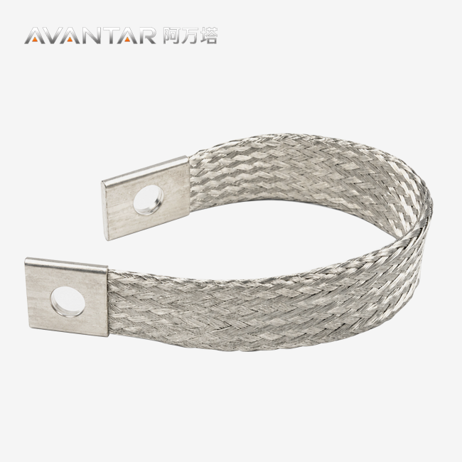
A flexible laminated copper busbar is a high-current connection made from multiple thin copper foils arranged into a flexible stack, with consolidated terminal areas at the connection points.
In battery energy storage systems, the challenge is not simply to choose enough copper cross-section. The connection must carry the required current without excessive temperature rise, fit inside a limited installation envelope, accommodate controlled movement, maintain stable terminal contact, and provide appropriate electrical insulation.
That makes ampacity, temperature rise and insulation design closely connected.
This guide explains how BESS engineering and sourcing teams should evaluate flexible laminated copper busbars from a thermal and electrical perspective—and what information should be defined before releasing a custom drawing for production.
Global energy-storage deployment continues to expand rapidly. BloombergNEF reported that annual additions reached 112 GW / 307 GWh in 2025, the first year in which global annual additions exceeded 100 GW. 彭博新能源财经
For BESS designers, that growth makes repeatable, verifiable high-current connections increasingly important.
What Is a Flexible Laminated Copper Busbar?
A flexible laminated copper busbar uses multiple copper foils to create a conductive section that can accommodate controlled mechanical movement between two terminals.
Compared with a rigid copper bar, the flexible section can help absorb:
- limited thermal expansion;
- assembly tolerance;
- small positional offsets;
- vibration within the designed movement direction.
At the same time, its flat geometry can provide a compact electrical connection inside battery racks, PCS cabinets and switchgear.
The conductor material should be defined by the project. Depending on the application, T2 copper or another project-specified copper grade may be used.
The exact foil construction, total cross-section, terminal geometry and insulation should be determined from the electrical and mechanical requirements—not from one universal catalog size.
Why Does Ampacity Matter in BESS Busbar Design?
Ampacity is the continuous current a conductor can carry under defined thermal conditions without exceeding the allowable temperature.
For a BESS busbar, the important phrase is:
under defined thermal conditions.
A copper cross-section does not have one fixed ampacity independent of its installation.
Current capability is influenced by:
- copper cross-section;
- conductor geometry;
- ambient temperature;
- enclosure airflow;
- insulation;
- surface condition;
- terminal resistance;
- neighboring heat sources;
- duty cycle;
- allowable temperature rise.
Published copper-busbar data from the Copper Development Association illustrate this clearly: allowable current changes with temperature rise, conductor arrangement and cooling conditions. (Copper Development Association)
For that reason, published busbar tables are useful engineering references, but they should not be treated as a universal rating table for every custom flexible laminated busbar.
Why Is Temperature Rise More Useful Than a Simple A/mm² Rule?
Electrical losses in a conductor follow:
P = I²R
As current increases, resistive heating increases with the square of current.
That means a small increase in resistance can become important in a high-current BESS connection.
It is tempting to specify a busbar using a simple rule such as:
current ÷ fixed A/mm² = required copper area
That can be useful for very early packaging studies, but there is no universal A/mm² value for flexible laminated copper busbars.
The final design should consider the actual temperature rise of the complete connection.
A Simple Preliminary Example
Consider a battery rack delivering:
250 kW at 1,000 V DC
The nominal continuous current is:
250,000 W ÷ 1,000 V = 250 A
That current provides a useful starting point for engineering.
But it does not yet tell us the final busbar width or thickness.
The next questions are:
What ambient temperature will the busbar see?
How much airflow is available?
Is the conductor insulated?
How large is the terminal area?
What temperature rise is acceptable?
Are there nearby heat-producing components?
What overload or peak-current duty must be considered?
Only after those conditions are known should the final conductor geometry be established and verified.
Where Can a Flexible Busbar Actually Run Hot?
The hottest point is not necessarily the middle of the flexible copper section.
Potential thermal bottlenecks often occur at:
- terminal pads;
- bolt interfaces;
- hole regions;
- changes in copper cross-section;
- plated contact surfaces;
- transitions between flexible and rigid sections.
A busbar can therefore have adequate total copper area while still developing excessive temperature at the connection interface.
This is why the complete current path should be evaluated.
Why Does Terminal Design Affect Ampacity?
The terminal connects the flexible conductor to another electrical component.
Its electrical performance depends on several interacting factors:
Net copper section around the holes. Bolt holes remove conductive material.
Contact area. The mating surfaces need enough effective contact area for the required current.
Surface condition. Oxidation, contamination or inappropriate finish can affect contact resistance.
Hardware and torque. Contact pressure changes electrical resistance at the interface.
Terminal geometry. Sharp reductions in width or thickness can create localized current-density and thermal effects.
For a drawing-based busbar, engineers should therefore review terminal geometry together with the conductor cross-section.
Flexible Laminated Busbar vs Rigid Copper Busbar
Flexible and rigid busbars solve different mechanical problems.
| Factor | Flexible Laminated Busbar | Rigid Copper Busbar |
|---|---|---|
| Mechanical behavior | Accommodates controlled movement | Maintains fixed geometry |
| Installation tolerance | More forgiving within designed flex zone | Requires closer terminal alignment |
| Packaging | Compact with a defined flexible section | Very compact where fixed routing is possible |
| Typical BESS role | Flexible interface between fixed components | Fixed distribution path |
| Main selection factors | Current + movement + geometry | Current + support + geometry |
Neither construction should automatically replace the other.
A practical BESS may use rigid busbars for fixed distribution and flexible laminated busbars only where movement or assembly tolerance needs to be accommodated.
How Should Insulation Be Selected?
Insulation is not simply a matter of choosing between “PVC, heat shrink or Kapton.”
Each material family contains different grades with different:
- dielectric strength;
- temperature capability;
- thickness;
- flexibility;
- flame behavior;
- abrasion resistance;
- chemical resistance.
For that reason, the insulation specification should identify the required performance, not just the material name.
Common Insulation Approaches
| Insulation approach | Main advantage | What should be confirmed |
|---|---|---|
| Polymer sleeve | Simple mechanical and electrical protection | Voltage rating, material grade, temperature capability, flexibility |
| Heat-shrink insulation | Conformal coverage around irregular geometry | Material grade, shrink ratio, dielectric requirement and operating temperature |
| Polyimide film or tape | Thin insulation for space-constrained designs | Film grade, dielectric strength, temperature rating and wrapping construction |
| Project-specific film or molded insulation | Optimized for defined OEM geometry | Full electrical, thermal and mechanical specification |
The important point is that temperature capability belongs to the exact insulation grade, not to the generic material family.
A purchasing specification should therefore avoid statements such as:
PVC = 105°C
Heat shrink = 125°C
Polyimide = 200°C
unless the actual supplied material data sheet supports those ratings.
How Do Voltage, Creepage and Clearance Affect Insulation?
Insulation around the copper conductor is only one part of the electrical insulation system.
The complete assembly must also consider:
- conductor-to-conductor clearance;
- conductor-to-ground clearance;
- creepage distance;
- terminal exposure;
- insulation overlap;
- contamination;
- humidity;
- system voltage.
If the busbar flexes, the designer should also verify that movement does not reduce the required electrical spacing.
For flexible busbars integrated into applicable low-voltage switchgear or controlgear assemblies, IEC 61439 requirements may be relevant at the complete assembly level.
IEC 61439-1:2020 covers general requirements for low-voltage switchgear and controlgear assemblies and includes DC and temperature-rise verification requirements. It should not be presented as a universal standalone certification for the individual custom busbar itself.
How Does Insulation Affect Thermal Performance?
Insulation can change how heat leaves the conductor.
A bare copper surface exposed to moving air behaves differently from the same conductor surrounded by insulating material inside a confined cabinet.
This means an insulated flexible busbar should not automatically inherit the same allowable current as a bare conductor with the same copper cross-section.
The design should consider:
- insulation thickness;
- insulation thermal properties;
- airflow;
- enclosure temperature;
- conductor orientation;
- spacing from neighboring conductors.
For high-current applications, the thermal effect of the final installed configuration matters more than the appearance of the conductor on a catalog page.
How Should Temperature Rise Be Verified?
Calculation is useful for initial design.
Verification provides confidence in the final connection.
A representative temperature-rise evaluation may include:
- Mounting the busbar between representative mating terminals.
- Installing the specified hardware and tightening procedure.
- Applying the required continuous current.
- Allowing the connection to reach thermal stabilization.
- Measuring temperature at the flexible section, terminal areas and bolted interfaces.
- Comparing the results with the applicable project or assembly acceptance criteria.
The test arrangement should represent the real installation as closely as practical.
An open-air test may not represent performance inside a compact BESS cabinet.
What About Voltage Drop and Connection Resistance?
Electrical resistance can also be evaluated directly.
For a high-current connection, useful measurements may include:
- low-resistance measurement across the connection;
- millivolt drop under defined current;
- temperature mapping;
- comparison before and after mechanical or thermal cycling.
These measurements can help identify an abnormal terminal, poor contact surface or manufacturing inconsistency.
The exact acceptance values should come from the project specification or validated product design rather than a universal internet value.
How Should Mechanical Movement Be Considered?
A flexible laminated busbar is not intended to behave like an unrestricted cable.
It works best when the required movement is understood.
A drawing should define, where relevant:
- lateral movement;
- axial displacement;
- angular movement;
- flexible length;
- bend direction;
- installation envelope.
The rigid terminal area should not become the primary hinge point.
If the connection needs substantial twisting or repeated multidirectional movement, a flexible copper braid connector may be a more appropriate starting point.
For a detailed comparison, see:
Laminated Busbar vs Copper Braid: Which Flexible Connection Fits BESS Better?
What Custom Parameters Should Be Defined on the Drawing?
A custom flexible laminated copper busbar should be treated as an engineering component.
The drawing should define the dimensions and interfaces needed to reproduce the part consistently.
Electrical Requirements
Include:
continuous current, peak current and duration where relevant, system voltage, target temperature rise and any short-time current requirement.
Mechanical Envelope
Define:
overall length, maximum width, maximum thickness, available installation space, terminal locations and expected movement.
Terminal Geometry
Specify:
hole diameter, hole quantity, center spacing, terminal dimensions, edge distances, bend geometry and mating hardware information.
Conductor
State:
required copper grade if already defined, and any restrictions on the conductor construction.
If the foil construction has not yet been engineered, it can be finalized during drawing review.
Surface Finish
Possible finishes may include:
bare copper, tin or silver.
Selection should depend on the mating terminal, corrosion environment, electrical interface and project requirement—not simply on current rating.
Insulation
Define:
required voltage performance, operating temperature, coverage area, exposed terminal length, color and any relevant flame or environmental requirement.
AVANTAR Drawing-Based Configuration
AVANTAR supports drawing-based flexible laminated copper busbar projects for BESS, PCS, switchgear and industrial power equipment.
A typical engineering review may cover:
| Design Item | Project-Based Configuration |
|---|---|
| Conductor | T2 copper or project-specified copper grade |
| Construction | Laminated copper foils |
| Total cross-section | Current- and thermal-design dependent |
| Width / thickness | Drawing- and installation-dependent |
| Terminal geometry | Flat, formed or custom hole pattern |
| Surface finish | Bare copper / tin / silver, subject to project |
| Insulation | Project-specific sleeve, heat-shrink or insulating film |
| Drawing input | 2D / 3D files accepted |
This keeps the product page, technical article and RFQ process aligned around the same principle:
the final configuration follows the application and approved drawing.
What Should Be Verified Before Approving a Custom Busbar?
The approval process should focus on measurable requirements rather than generic claims about “high quality.”
A useful review typically considers:
Drawing accuracy.
Dimensions, holes, terminal geometry and bend positions match the approved drawing.
Material definition.
The agreed copper grade and surface treatment are documented.
Electrical performance.
Resistance, voltage drop or temperature rise is checked when required by the project.
Terminal integrity.
The consolidated terminal area and mating interface are suitable for the intended hardware and load.
Insulation.
Material and coverage meet the defined voltage, temperature and mechanical requirements.
Traceability and documentation.
Required dimensional, material or inspection documentation is defined before production.
This creates a much stronger procurement basis than simply asking whether a supplier has “CE, UL and ISO.”
How Should Standards Be Used?
Standards should be connected to their actual scope.
IEC 61439
IEC 61439 applies to low-voltage switchgear and controlgear assemblies.
It may therefore be relevant when a busbar becomes part of an applicable BESS distribution, PCS or switchgear assembly.
It should not automatically be advertised as a product certification for an individual custom flexible busbar.
UL 486A-486B
UL 486A-486B covers defined categories of wire connectors. The current fourth edition was published in March 2025. Its scope includes specified pressure wire connectors and related connector applications; it is not a universal certification for every laminated busbar geometry. UL Standards Online
If a North American project references UL requirements, the exact connection or component requiring evaluation should be identified.
Environmental Testing
Where vibration or temperature cycling is part of a project validation plan, standards such as IEC 60068-2-6 for sinusoidal vibration and IEC 60068-2-14 for temperature-change testing can provide standardized test methods. IEC Webstore
The test severity and acceptance criteria still need to be defined by the relevant project specification.
A Recommended Drawing-to-Production Workflow
A practical custom busbar workflow can follow seven stages:
- Requirement input — current, voltage, operating environment, installation envelope and movement are defined.
- Drawing review — terminal geometry, flexible section, hole positions and manufacturing feasibility are reviewed.
- Material and configuration confirmation — copper grade, finish, insulation and relevant project requirements are agreed.
- Sample or first article — used where project risk or customization justifies physical verification.
- Verification — dimensional, electrical, thermal or insulation checks are performed as required by the project.
- Drawing approval — the approved configuration becomes the production reference.
- Production and inspection — production is controlled against the agreed drawing and inspection scope.
Not every project requires every test.
The important point is that the verification plan should be agreed before production, rather than added after a problem appears.
What Information Should Be Included in an RFQ?
For a useful technical quotation, provide:
- continuous current;
- peak current and duration if relevant;
- system voltage;
- ambient and enclosure conditions;
- available installation space;
- terminal locations;
- hole pattern;
- required movement;
- preferred surface finish;
- insulation requirement;
- applicable standards or customer specifications;
- 2D drawing and preferably a 3D model.
This gives the supplier enough information to propose a busbar that can actually be reviewed, tested and approved.
FAQ
Is there a standard A/mm² value for flexible laminated copper busbars?
No. Current density can be useful for preliminary sizing, but there is no universal A/mm² value that applies to every BESS installation. Final current capability depends on conductor geometry, temperature rise, terminals, ambient conditions, airflow, insulation and duty cycle.
How do I calculate the required copper cross-section?
Start with continuous and peak-current requirements, then consider the thermal environment and available installation space. A preliminary cross-section can be estimated during early design, but final dimensions should be confirmed through thermal analysis, reference data or representative testing.
Does insulation reduce busbar ampacity?
It can. Insulation changes heat transfer from the copper conductor to the surrounding environment. The actual effect depends on insulation material, thickness, airflow, enclosure conditions and conductor geometry.
Which insulation is best for BESS flexible busbars?
There is no single best material. Polymer sleeves, heat-shrink materials and polyimide films each offer different advantages. Selection should be based on voltage, temperature, mechanical flexibility, thickness, abrasion, flammability and the exact material grade.
Can AVANTAR produce a busbar from my own drawing?
AVANTAR supports drawing-based flexible laminated copper busbar projects. Customers can provide electrical requirements together with 2D or 3D drawings covering dimensions, terminal geometry, surface finish, insulation and installation constraints for technical review.
Does a flexible laminated busbar need UL or CE certification?
Not automatically. Compliance depends on the product, complete assembly, target market and applicable regulations or standards. Requirements should be confirmed project by project rather than applying generic CE or UL statements to every custom busbar.
Conclusion
The ampacity of a flexible laminated copper busbar cannot be reduced to one width, one copper cross-section or one A/mm² rule.
For BESS applications, reliable selection requires the complete connection to be considered:
current → resistance → temperature rise → terminal interface → insulation → installation environment → verification
Insulation should also be specified by actual electrical, thermal and mechanical performance—not simply by a generic material name.
The strongest custom design therefore begins with the electrical duty and installation conditions, turns those requirements into a controlled drawing, and verifies the final connection against the project requirements.
That approach gives BESS engineering and procurement teams a far more reliable basis for approving a production part.
Turn Your BESS Requirements Into a Drawing-Based Busbar
AVANTAR supplies drawing-based flexible laminated copper busbars for BESS, battery racks, PCS, switchgear and other high-current power connections.
For technical review, send your:
current requirements + installation envelope + terminal drawing + insulation requirements + operating conditions
to:
AVANTAR
AVANTAR (GUANGDONG) INDUSTRIAL HOLDINGS CO., LTD.
References
-
BloombergNEF — Energy Storage Enters the 100-Gigawatt Era: Three Things to Know
2025 global energy-storage additions reached 112 GW / 307 GWh. 彭博新能源财经 -
Copper Development Association — Ampacities of Copper Busbars
Reference material for copper-busbar ampacity, geometry and temperature-rise behavior. -
IEC 61439-1:2020 — Low-voltage switchgear and controlgear assemblies, Part 1
Relevant to applicable complete low-voltage assemblies and assembly-level verification. -
IEC 60068-2-6:2007 — Environmental Testing, Vibration (Sinusoidal)
Standardized sinusoidal-vibration test method. IEC Webstore -
IEC 60068-2-14:2023 — Environmental Testing, Change of Temperature
Standardized temperature-change test methods. IEC Webstore -
UL 486A-486B, Edition 4 — Wire Connectors
Used only to clarify the scope of connector-specific UL requirements. UL Standards Online -
International Energy Agency — Batteries and Secure Energy Transitions
The IEA estimates that global energy-storage capacity needs to increase to around 1,500 GW by 2030 in its NZE pathway, with batteries accounting for roughly 1,200 GW. IEA
Technical Review: AVANTAR Technical Team
Learn about our latest products and discounts through SMS or email