Laminated Busbar vs Copper Braid: Which Flexible Connection Fits BESS Better?
For most BESS projects, the choice between a flexible laminated copper busbar and a flexible copper braid connector should not start with a catalog current rating.
It should start with the connection itself.
A laminated busbar is usually a strong starting point when the connection needs to carry high current through a compact, repeatable route with controlled movement. Copper braid becomes more attractive when the joint must accommodate greater multidirectional movement, vibration, twist, or installation misalignment.
Neither construction is automatically “better.” The right choice depends on electrical load, temperature rise, terminal geometry, available space, movement direction, vibration, surface finish, insulation, and the way the complete assembly will be verified.
This guide compares both flexible connection types from a BESS engineering and sourcing perspective.
What Is a Flexible Laminated Copper Busbar?
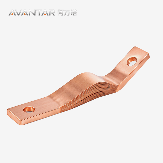
A flexible laminated copper busbar is made from multiple thin copper foils arranged into a flexible stack, with consolidated terminal regions at the connection points.
Unlike a rigid solid copper bar, the laminated section can accommodate controlled movement between connected components. At the same time, its flat geometry makes it suitable for compact electrical assemblies where routing space is limited.
In BESS equipment, laminated flexible connections may be considered for:
- battery module connections;
- battery rack DC connections;
- PCS interfaces;
- switchgear and DC distribution assemblies;
- other short, high-current connections with defined geometry.
The exact copper grade, foil construction, cross-section, terminal design and insulation should be matched to the project rather than selected from a generic catalog specification.
What Is a Flexible Copper Braid Connector?
A flexible copper braid connector uses woven copper strands to create a flexible electrical link between two connection points.
The braided structure can move more freely than a formed laminated stack, particularly when the connection experiences movement in several directions.
Copper braid is often considered where the installation needs to accommodate:
- vibration;
- angular movement;
- multidirectional displacement;
- alignment variation;
- movement between independently mounted equipment.
The braid itself is only one part of the design. Effective copper cross-section, end-terminal construction, surface finish, support, insulation and installation geometry all influence the final electrical and mechanical performance.
Laminated Busbar vs Copper Braid: What Is the Main Difference?
The most useful distinction is mechanical behavior.
| Decision factor | Flexible laminated busbar | Flexible copper braid |
|---|---|---|
| Main movement behavior | Controlled movement along a planned geometry | Greater multidirectional compliance |
| Packaging | Flat, compact and repeatable | More adaptable to irregular routing |
| Terminal geometry | Highly repeatable, drawing-based pads | Compacted, welded or terminalized ends |
| Assembly consistency | Well suited to repeated OEM layouts | More tolerant of installation variation |
| Typical BESS use | Rack, module, PCS or compact power connection | Vibration-sensitive or moving interface |
| Engineering priority | Geometry + current + controlled flex | Movement + current + fatigue behavior |
This does not mean laminated busbars cannot tolerate vibration, or that braid cannot carry high current.
It means each construction solves a different mechanical problem.
Which One Handles Higher Current?
Neither construction has a universal current advantage simply because it is “laminated” or “braided.”
Current capability depends on the effective copper cross-section, conductor temperature, terminal resistance, cooling conditions, surface area, installation environment, and duty cycle.
Copper busbar ampacity data published by the Copper Development Association show that temperature rise, conductor arrangement, emissivity and cooling conditions can materially change allowable current. That is why current rating should not be selected from width alone. 铜业协会
For a compact BESS connection, laminated copper often provides a practical way to create a broad conductive section within a limited installation envelope.
Braid can also be designed for substantial current, provided adequate copper section and properly designed terminals are used.
Why Is Temperature Rise More Important Than a Simple Amp Rating?
Electrical losses follow the relationship:
P = I²R
As current increases, even a relatively small increase in resistance can generate significantly more heat.
That resistance is not limited to the flexible conductor itself. The complete current path also includes:
terminal pads, plating, bolt interfaces, mating conductors, washers or hardware, and local reductions in copper cross-section.
For this reason, engineers should evaluate the complete connection rather than comparing two conductors only by nominal width or cross-section.
Which Connection Is Better for Battery Rack Packaging?
A laminated busbar is often easier to integrate when the route needs to be flat, compact and repeatable.
Battery racks frequently have limited space between modules, structural frames, switching components and enclosure surfaces. A drawing-based laminated busbar can follow a defined geometry and repeat the same terminal locations across multiple racks.
Copper braid has greater routing freedom, but that same freedom can make the installed geometry less controlled.
For low-volume equipment or locations with large assembly tolerances, that may be useful.
For repeat production where hole location, bend position and installation envelope need to remain consistent, laminated construction is often a better starting point.
Which Connection Handles Movement Better?
This is where copper braid has its strongest advantage.
Braided copper is well suited to applications involving:
- repeated vibration;
- twist;
- multidirectional movement;
- uncertain alignment;
- movement between separately mounted components.
A laminated flexible busbar is better suited to planned movement.
Its geometry can be designed to accommodate a known offset, thermal expansion direction or installation tolerance.
The key question is therefore not:
“Which conductor is more flexible?”
The better question is:
“What movement must this connection accommodate, in which direction, and how often?”
What Does Controlled Flex Mean for a Laminated Busbar?
The flexible foil section allows limited movement between the two terminal areas.
That movement should occur primarily within the designed flexible zone—not at the rigid terminal interface.
A good drawing should therefore identify:
available flexible length, intended bend direction, expected displacement, installation envelope, terminal position, and any movement that may occur during operation or servicing.
If significant twisting or repeated multidirectional movement is expected, braid may be the more suitable starting point.
How Should Vibration Be Evaluated?
“Vibration resistant” is too vague to be a useful engineering requirement.
A better specification defines the expected vibration profile, direction, frequency range, duration, mounting condition and acceptance criteria.
IEC 60068-2-6 provides a standardized method for sinusoidal vibration testing of components and equipment. It can be useful when a project needs a defined vibration-test method, but the actual test severity and acceptance criteria still need to come from the relevant product or project specification. IEC Webstore
Likewise, IEC 60068-2-14 provides methods for evaluating specimens under specified temperature changes. These tests can help reveal changes in mechanical or electrical behavior caused by temperature cycling, but they do not by themselves establish complete field life. IEC Webstore
For a BESS connection, vibration and temperature testing are most useful when combined with representative electrical loading.
Which Connection Has Better Thermal Performance?
There is no universal answer.
A laminated busbar can offer a broad, flat conductive path and controlled terminal geometry.
Braid can provide a large effective copper section while maintaining mechanical flexibility.
The final temperature depends on the whole connection.
Important variables include:
effective copper section, terminal construction, contact resistance, surface finish, ambient temperature, enclosure airflow, conductor spacing, neighboring heat sources, and current duty.
A conductor that performs well in open air may behave differently inside a crowded battery cabinet.
Where Do Hot Spots Usually Matter Most?
Engineers should pay particular attention to transition areas:
- terminal pads;
- bolt interfaces;
- hole regions;
- plated contact surfaces;
- braid-to-terminal transitions;
- changes in conductor cross-section.
These areas can create localized resistance even when the main flexible section has adequate copper.
For a new design, voltage-drop or resistance measurements and temperature mapping under representative current can provide much more useful information than relying on a catalog ampacity alone.
How Should IEC 61439 Be Used in a BESS Busbar Project?
IEC 61439-1 addresses general requirements for low-voltage switchgear and controlgear assemblies, including construction and verification requirements.
The 2020 edition also includes DC-related requirements and places emphasis on temperature-rise verification within loaded assemblies. IEC Webstore
That makes it relevant when a flexible connection is incorporated into applicable switchgear, PCS or distribution assemblies.
However, IEC 61439 should not be presented as a universal standalone certification for an individual custom laminated busbar or braid connector.
The correct approach is:
evaluate the connection within the requirements of the complete assembly and the applicable project standard.
When Is Copper Braid the Better Starting Point?
Copper braid deserves serious consideration when mechanical movement is the dominant design constraint.
Typical indicators include repeated vibration, rotational movement, uncertain alignment, independently mounted equipment, servicing movement, or a connection route that would force excessive stress into a laminated busbar.
For example, braid may be a useful starting point for:
transformer-related flexible connections, vibration-sensitive equipment interfaces, moving panels or service connections, and bonding applications.
The final design still needs electrical sizing, terminal review, environmental evaluation and mechanical validation.
When Is a Flexible Laminated Busbar the Better Starting Point?
A flexible laminated copper busbar is especially suitable when the connection needs:
high current, limited installation space, repeatable terminal positions, a controlled route, and a defined amount or direction of movement.
Typical applications include battery-rack connections, module-to-distribution links, PCS interfaces and selected switchgear connections.
For OEM production, the drawing-controlled geometry can also reduce installation variation from one assembly to the next.
Can a BESS Use Both Laminated Busbars and Copper Braid?
Yes—and in many systems that is more logical than trying to force one conductor type into every location.
A BESS may use:
rigid copper busbars for supported fixed distribution;
flexible laminated busbars where a compact high-current path requires controlled movement;
and copper braid connectors where multidirectional vibration or mechanical movement dominates.
The conductor should follow the mechanical and electrical function of each interface.
This is a better design principle than attempting to standardize every flexible connection around one construction.
AVANTAR Drawing-Based Configuration
For flexible laminated copper busbar projects, AVANTAR works from the actual connection geometry and electrical requirements rather than a single generic size range.
| Design item | Drawing-based configuration |
|---|---|
| Conductor | T2 copper or project-specified copper grade |
| Flexible section | Laminated copper foils |
| Width / cross-section | Current- and drawing-dependent |
| Terminal geometry | Flat, formed or custom hole pattern |
| Surface finish | Bare copper / tin / silver, subject to project |
| Insulation | Project-specific sleeve, heat-shrink or insulating film |
| Drawing input | 2D / 3D drawings accepted |
For copper braid connectors, the same drawing-based principle applies: required current, cross-section, flexible length, terminal geometry, hole pattern, finish and movement requirements should be defined together.
How Should Surface Finish Be Selected?
Bare copper, tin and silver can all be appropriate depending on the connection.
Selection should consider mating material, corrosion environment, contact design, service conditions and the customer's specification.
A high current value by itself does not automatically mean silver plating is necessary.
Likewise, tin plating should not be specified automatically for every BESS connection.
The finish should be treated as part of the overall interface design.
What About UL 486A-486B?
UL 486A-486B covers defined categories of wire connectors, including several pressure, splicing and other connector types. Its official scope does not make it a universal certification standard for every custom laminated busbar. UL Standards Online
If a North American project references UL requirements, the buyer and supplier should identify exactly which component or interface falls within the required scope.
This is more reliable than simply writing “UL compliant” on a generic flexible conductor.
What Should Be Included in a BESS Flexible-Connection RFQ?
A strong RFQ should allow the supplier to understand both the electrical and mechanical problem.
Include:
Electrical duty: continuous current, peak current, peak duration, system voltage and allowable temperature rise.
Installation envelope: available length, width, thickness and surrounding clearance.
Movement: expected direction, displacement, vibration, twist or service movement.
Terminal interface: hole diameter, hole spacing, terminal dimensions, mating material and hardware.
Conductor requirements: copper grade where specified and any required cross-section or construction limitations.
Surface finish: bare, tin, silver or project-specific finish.
Insulation: electrical requirement, coverage, operating temperature and exposed terminal length.
Environment: ambient temperature, airflow, humidity, corrosion exposure and enclosure conditions.
Verification: electrical, thermal, vibration, temperature cycling or other project-specific acceptance requirements.
Drawing: dimensioned 2D drawing and, where available, a 3D model.
That information gives an engineering supplier enough context to recommend laminated foil, braid, rigid copper or a combination of the three.
Practical Decision Guide
| Application condition | Better starting point | Confirm before release |
|---|---|---|
| Tight space + repeatable terminals | Flexible laminated busbar | Cross-section, bend direction, terminal geometry |
| Controlled thermal movement | Flexible laminated busbar | Flexible length and displacement |
| Repeated multidirectional vibration | Copper braid | Movement, fatigue, support and terminal construction |
| Significant twist or service movement | Copper braid | Slack, routing and mechanical protection |
| Long fixed distribution path | Rigid copper busbar | Supports, temperature rise and fault duty |
| Fixed system with one moving interface | Hybrid design | Transition geometry and interface loading |
The phrase “starting point” matters.
Final selection should still be verified against the actual electrical load, movement and installation conditions.
FAQ
Is a flexible laminated copper busbar the same as a copper braid connector?
No. A laminated flexible busbar uses stacked copper foils and controlled terminal geometry. Copper braid uses woven copper strands and generally provides greater multidirectional flexibility. Both can carry substantial current when correctly designed.
Which is better for battery rack connections?
For a short, compact connection with repeatable terminals and controlled movement, a flexible laminated busbar is often the better starting point. If the interface has substantial vibration, twist or multidirectional movement, copper braid may be more suitable.
Can current capacity be determined from busbar width alone?
No. Width does not account for total copper cross-section, temperature rise, terminals, contact resistance, airflow, duty cycle or ambient conditions. Current capability should be assessed for the complete connection.
Which one is better for vibration?
Copper braid generally provides greater multidirectional mechanical compliance. Laminated busbars can accommodate controlled movement and vibration when the flexible zone is properly designed.
Can AVANTAR customize both laminated busbars and braid connectors?
AVANTAR supports drawing-based flexible power-connection projects. For laminated busbars and copper braid connectors, dimensions, terminals, hole pattern, surface treatment and other project requirements can be reviewed against the customer's application and drawing.
Can laminated busbars and copper braid be used in the same BESS?
Yes. Using different conductor types at different interfaces can be the better engineering solution. Rigid busbars, laminated flexible connections and braid can each serve the locations best suited to their mechanical behavior.
Conclusion
The question is not simply:
“Laminated busbar or copper braid—which is better?”
The better question is:
“What electrical load and mechanical movement does this particular connection need to handle?”
Choose a flexible laminated copper busbar as the starting point when the BESS requires a compact, high-current and repeatable connection with controlled movement.
Choose copper braid when multidirectional vibration, twist or repeated movement is the dominant requirement.
And when the system contains both types of interfaces, use both.
The most reliable decision comes from reviewing the load profile, installation envelope, movement path, terminal design, environment and verification plan together before freezing the drawing.
Turn Your BESS Connection Requirements Into a Reviewable Drawing
AVANTAR supplies drawing-based flexible laminated copper busbars and flexible copper braid connectors for BESS, PCS, switchgear and industrial power applications.
Send your current requirement, installation envelope, terminal dimensions and movement requirements to:
AVANTAR
AVANTAR (GUANGDONG) INDUSTRIAL HOLDINGS CO., LTD.
References
- Copper Development Association, Ampacities and Mechanical Properties of Rectangular Copper Busbars. Used for copper-busbar ampacity and thermal-design context. 铜业协会
- IEC 61439-1:2020, Low-voltage switchgear and controlgear assemblies – Part 1: General rules. Used for assembly-level DC and verification context. IEC Webstore
- IEC 60068-2-6:2007, Environmental testing – Test Fc: Vibration (sinusoidal). Used for vibration-test methodology. IEC Webstore
- IEC 60068-2-14:2023, Environmental testing – Test N: Change of temperature. Used for temperature-change test methodology. IEC Webstore
- UL 486A-486B, Edition 4, Wire Connectors. Used only to clarify the standard's connector scope. UL Standards Online
Technical Review: AVANTAR Technical Team
Learn about our latest products and discounts through SMS or email