Earthing Copper Busbar
2. Finish: bare copper or tin-plated.
3. Structure: flat busbar with multiple connection holes.
4. Connection holes: for M6, M8, M10 or M12 bolts, or custom sizes.
5. Mounting: insulator supports or brackets.
6. Cross-section and hole layout: to project drawing.
7.Lead Time: 7–10 working days
8.Customization: Flexible OEM/ODM options
Earthing Copper Busbar for Switchgear & Industrial Grounding Systems
Picking the correct grounding conductor is important for both safety and the long-term dependability of the system. Avantar makes earthing copper busbar systems out of T2 copper. They come in custom lengths up to 3,000 mm and cross-sections from 20x3 mm to 120x10 mm. Different hole patterns can fit sizes of M6, M8, M10, and M12. You can choose between a bare copper or tinned finish for the surface. The goods are in line with ISO 9001, CE, RoHS, IEC 62561, and IEC 61439-1/-2 standards.
What Is an Earthing Copper Busbar?
A product is a flat copper wire with holes already drilled in it so that it can be connected to other wires to make a common ground point in electrical panels, switchgear cabinets, and power distribution systems. It safely directs fault current away from people and equipment during short circuits, lowering dangerous contact voltages and keeping connected parts safe.
Avantar grounding bars are made from T2 copper, which is a very good conductor. When you use CNC to drill and cut, you get clean holes with consistent sizes and smooth surfaces that fit together well, so you can place it reliably in either a horizontal or vertical position.
Key Features
The high conductivity T2 copper makes the contact resistance low, which lowers the heat production in both normal and fault situations.
You can get bars in either bare copper or tinned form. The tinplate's surface makes it more resistant to corrosion, and it works well in humid places, like data center power cabinets and industrial sites near the coast.
Standard or unique spacing CNC-drilled holes in M6, M8, M10, or M12 shapes to fit the way your panel is set up. The flat bar form lets the installation be done with either an insulator or a bracket.
The mounting insulators, connectors, and tools are all made of stainless steel, and the whole set can be sent to you.
Applications
- Low-voltage switchgear and MCC panels — unified grounding connection points for breakers, instrument transformers, and cable shields
- Data center power cabinets — stable earthing potential across high-density power distribution units
- Energy storage systems — fault current protection for battery enclosures and inverter cabinets
- Renewable energy projects — solar inverter stations and wind turbine junction boxes
- Industrial electrical systems — motor control centers, transformer substations, and distribution boards
- Infrastructure projects — tunnels, rail transit, and building electrical systems
Technical Specifications
| Parameter | Details |
|---|---|
| Material | T2 copper |
| Surface Treatment | Bare copper or tinned |
| Cross-Section Range | 20×3 mm to 120×10 mm typical |
| Common Sizes | 20×3, 30×4, 40×5, 50×5, 60×6, 80×8, 100×10 mm |
| Hole Diameter | M6, M8, M10, M12 or custom |
| Max Custom Length | Up to 3,000 mm |
| Mounting Method | Insulator supported or bracket mounted |
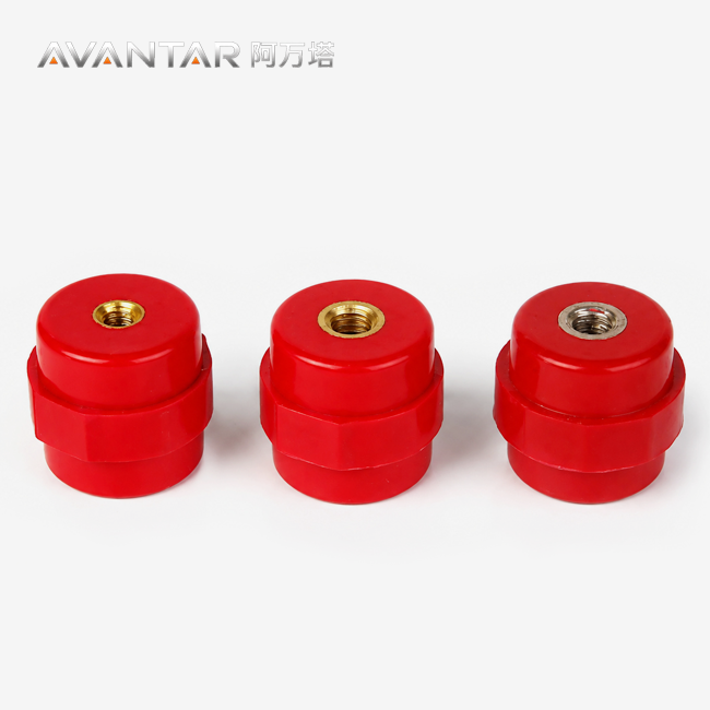
| Insulator Material | BMC/SMC or PA66+GF, UL94 V-0 flame retardant, CTI ≥ 600 V |
| Insulator Height Options | 40 mm, 50 mm, 60 mm, 80 mm (custom range 30–100 mm) |
| Lead Time | 7–15 working days |
Cross-section sizing follows the IEC 60364-5-54 formula S = (I × √t) / k, where k = 226 for tinned copper. For reference: 75 mm² suits small cabinets up to 25 kA; 200 mm² covers medium switchgear up to 50 kA; 360 mm² handles large switchgear up to 80 kA.
Custom Configuration Options
Avantar supports full customization to match specific switchgear or panel layouts. Available options include:
- Mixed multi-size hole layouts on a single bar
- L-shaped bent bars for corner or tight-space installation
- Multi-tier parallel bar structures for high-current applications
- Custom insulator heights from 30 mm to 100 mm
- Laser marking for PE or EARTH identification
- Yellow-green heat-shrink sleeves for color-coded grounding identification
You can submit grounding layout drawings directly. The workflow runs from drawing submission to assembly drawing confirmation, then sample production, and finally mass delivery.
Compliance & Quality Standards
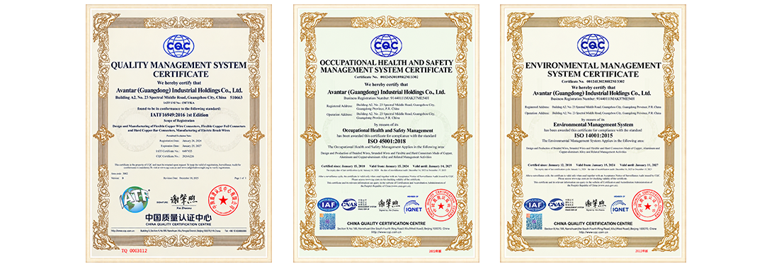
The products comply with the standards ISO 9001, CE, RoHS, IEC 62561, IEC 61439-1/-2, IEC 60364-5-54. Tests include: conductivity of copper bars, insulator dielectric withstand, CTI tracking index, temperature rise, short-circuit mechanical withstand and salt-spray resistance of tin-plating. Each shipment shall be accompanied with a declaration of conformity and a batch test report.
How to Specify?
To select the correct earthing copper busbar for your project, confirm the following parameters before ordering:
- Prospective fault current (kA) and protection device clearing time (seconds) — determines required cross-section per IEC 60364-5-54
- Panel or cabinet dimensions — length, width, and available mounting space
- Number and size of connection holes — cable sizes, connector types, and spacing
- Surface treatment — bare copper or tinned, based on environment and corrosion exposure
- Mounting method — insulator-supported (specify height) or bracket-mounted
- Special requirements — color coding, laser marking, bent configuration, or multi-tier structure
If you are unsure which cross-section applies to your fault current level, send your system parameters to [email protected] and our technical team will provide a specification recommendation.
FAQ
Q: What kind of thing has a protected base, and where would you use it?
A: It's a grounding assembly that is used in power distribution cabinets, MCC panels and low voltage switchgear. The insulating base electrically separates the copper bar from the cabinet shell and also provides a single point of connection for breakers, instrument transformers, cable shields and cabinet doors. It carries the fault current in a short circuit, and reduces the voltage to a safe contact voltage.
Q: What are the cross-section sizes?
A: Generally cross sections range from 20x3 mm to 120x10 mm. Typical sizes are 20x3, 30x4, 40x5, 50x5, 60x6, 80x8 and 100x10 mm. We manufacture custom cross-sections. Lengths up to 3,000 mm.
Q: How do I choose the proper cross section for my fault current?
A: Use the IEC 60364-5-54 formula: S = (I × √t) / k, where k = 226 for tinned copper. 75 mm2 for less than 25 kA current cabinets, 200 mm2 for medium switchgear with less than 50 kA current, 360 mm2 for large switchgear with less than 80 kA current.
Q: Can I specify hole designs, insulator heights, different connection configurations?
A: Yes. It can take mixed multi-size hole arrangement, L-shaped bent bars and multi-tier parallel structures. The BMC/SMC or PA66+GF material makes it possible to vary the height of the insulator from 30mm to 100mm. You may also be able to purchase laser labelling and yellow-green heat shrink sleeves.
Q: What tests and standards are used?
A: The product complies with ISO 9001, CE, RoHS, IEC 60364-5-54 and IEC 61439-1/-2. Conductivity test, dielectric withstanding, CTI index, temperature rise, short-circuit mechanical withstanding, salt spray resistance. Test records and statement of conformance are provided with every order.
Q: How long is the wait time?
A: The normal lead time is between 7-15 working days once the drawing is accepted. You can acquire some samples to test before mass production begins.
Contact Us
For Earthing Copper Busbar project requirements, drawings, or specification questions, contact us at [email protected]. We will respond within one business day.
Learn about our latest products and discounts through SMS or email